跳至主要内容

Yanhua Digimaster 3 Honda Fit Hybrid 2015 Wiring Diagram

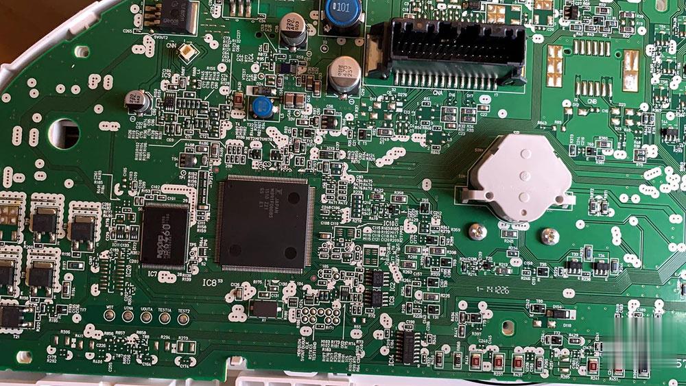
Hi, this is Honda Fit Hybrid 2015. I’m trying to do Mileage Correction. Please tell me correct position of each wire in CPU socket of ICP adapter to do correction mileage? Please mark each wire color in this picture.

Can you please tell me correct position of each wire of CPU socket of ICP adapter. Please kindly mark each wire color in picture.

I’m using Yanhua Digimaster 3 but this cluster have no small chip to use OBP adapter.

For this cluster need to soldering CPU socket wires of ICP adapter but actually I’m not sure where to soldering correct wire to correct point.
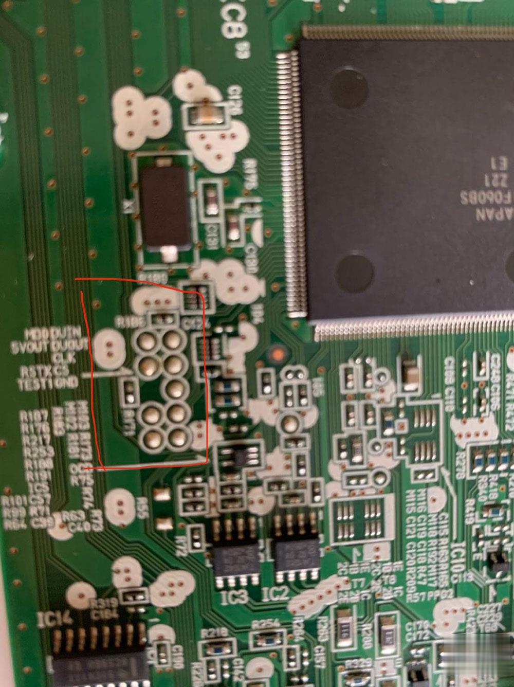
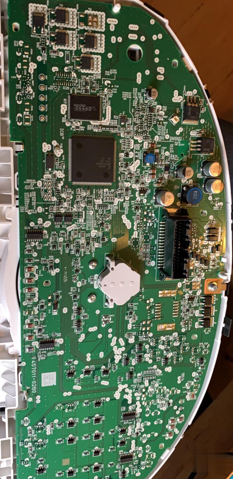
Yanhua-Digimaster-3-Honda-Fit-Hybrid-2015-Wiring-Diagram-1 (2)Yanhua-Digimaster-3-Honda-Fit-Hybrid-2015-Wiring-Diagram-2 (2)
Yanhua-Digimaster-3-Honda-Fit-Hybrid-2015-Wiring-Diagram-3 (2)
Yanhua-Digimaster-3-Honda-Fit-Hybrid-2015-Wiring-Diagram-4 (2)

M891F062BS

Yanhua-Digimaster-3-Honda-Fit-Hybrid-2015-Wiring-Diagram-5 (2)

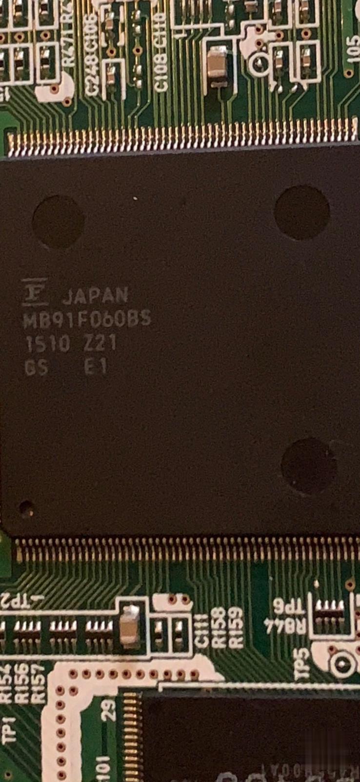
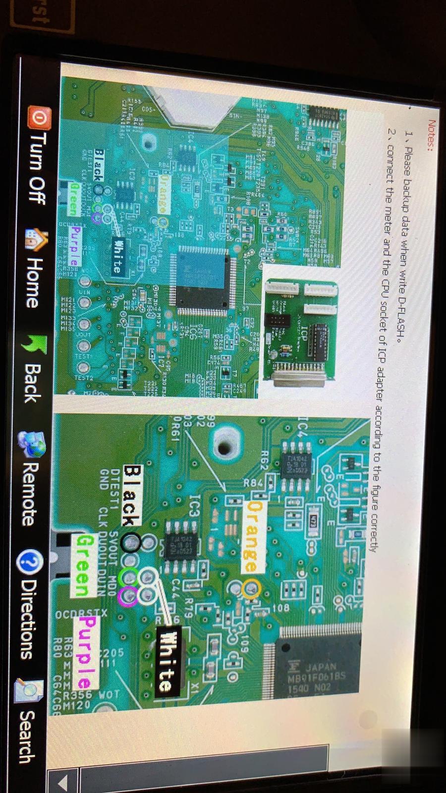
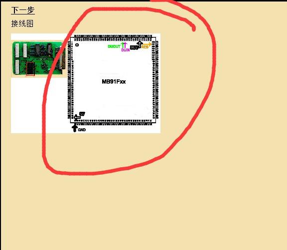
Compare it to the definition diagram of the CPU.

Use the buzzer file of the multimeter to measure the point where you follow the color of the CPU connection line as indicated in the picture. Put one end of the multimeter on the CPU pin and the other end at this position. As long as the multimeter alarms, solder the color of the line marked on the picture.

Yanhua-Digimaster-3-Honda-Fit-Hybrid-2015-Wiring-Diagram-6 (2)
Yanhua-Digimaster-3-Honda-Fit-Hybrid-2015-Wiring-Diagram-7 (2)
Yanhua-Digimaster-3-Honda-Fit-Hybrid-2015-Wiring-Diagram-8 (2)

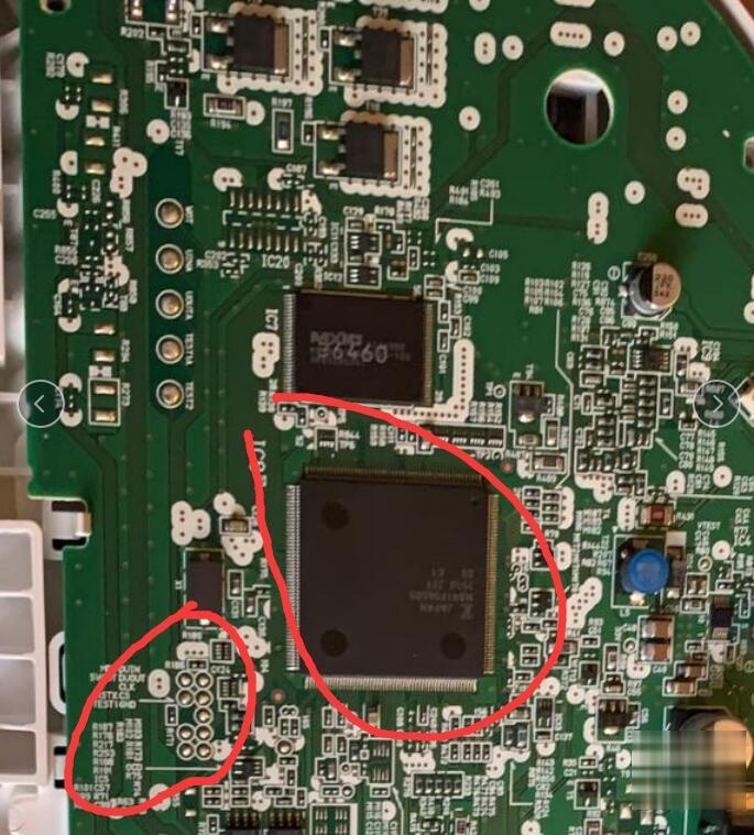
You solder according to the color of the line on this picture. Use a multimeter to find the solder joints of the corresponding welding line.

Yanhua-Digimaster-3-Honda-Fit-Hybrid-2015-Wiring-Diagram-9 (2)

So, it is unnecessary to connect with electric current when I’m using multimeter.

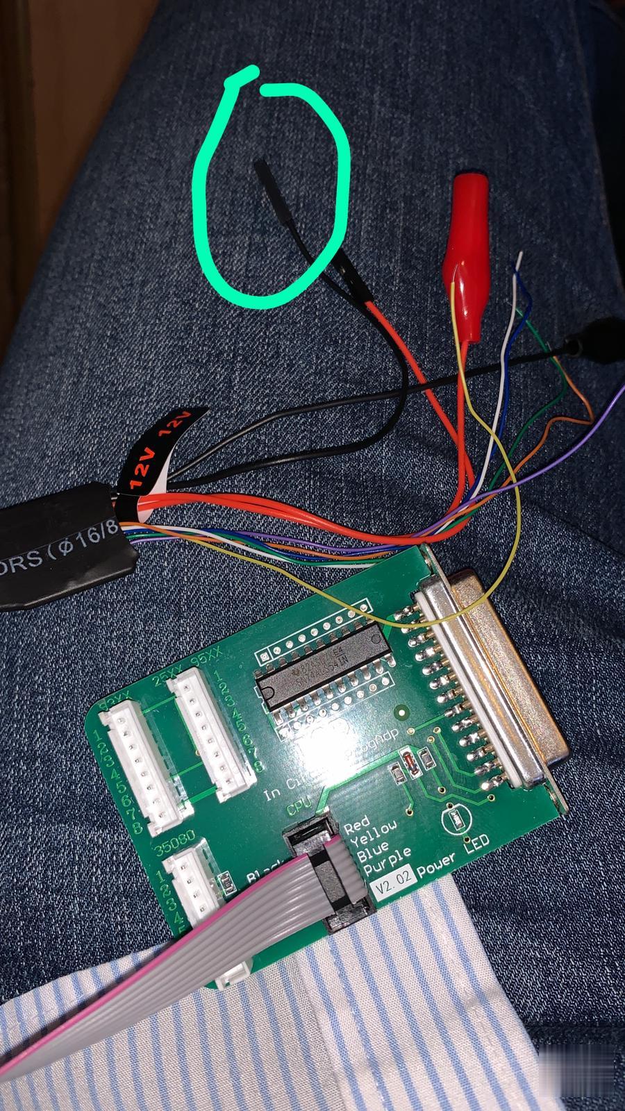
If I cut the black wire head so still will work.

Yanhua-Digimaster-3-Honda-Fit-Hybrid-2015-Wiring-Diagram-10 (2)

Hope it helps!

https://yanhuadigimaster3.blogspot.com/2021/08/yanhua-digimaster-3-honda-fit-hybrid.html

评论

此博客中的热门博文

How to Replace and Reprogram Chrysler FCM with DRB III

  SUBJECT: Replacing or reprogramming the Front Control Module (FCM) OVERVIEW: Erroneous Actuation of Horns, Headlamps, and Parking Lamps while vehicle is parked MODELS: 2001 – 2004 (RG) Chrysler Voyager (International Markets) 2001 – 2004 (RS) Town & Country/Caravan/Voyager SYMPTOM/CONDITION: While the vehicle is parked the customer may experience the horn sounding on and off, flashing the headlamps and the parking lamps as if the security alarm was actuated. The technician may find the vehicle is not equipped with Security Alarm system (sales code LSA). DIAGNOSIS: 1. Using a Scan Tool (DRBIII®) with the appropriate Diagnostic Procedures Manual, verify all engine systems are functioning as designed. If DTCs are present record them on the repair order and repair as necessary before proceeding further with this bulletin. 2. Determine the “Hardware Part #” of the FCM. Using the DRB III select: 3. DRBIII Standalone 4. 1998 – 2005 Diagnostics 5. All 6. Body In...

How to install john deere service advisor 4.2.005 on win 10 64bit

  John deere EDL V2 diagnostic kit with Service Advisor EDL V2 V4.2 Software, you can view service manuals, use DTAC (Technical Assistance Center) data, make diagnostics, readings, tests and calibrations, re-program controllers. John Deere EDL V2 Highlight 1. John Deere Service Advisor EDL (Electronic Data Link) heavy duty diagnostic adapter for construction equipment, agriculture, engines For John Deere. 2. John Deere Diagnostic kit includes software For John Deere Service Advisor 4.0 Agriculture or Construction and Forestry version. 3. John Deere Service Advisor 4.0 Agriculture workshop service manual, repair manual, electrical wiring diagram, hydraulic diagram, diagnostic, assembly and disassembly engine, transmission. 4. John Deere AG Management Solutions, Attachments, Backhoes, Combines and Headers, Cotton Harvestings, Excavators, ForkLifts, Hay and Forages, MAte Hand Cut and Shredderses, Plantings and Seedings, Skid Steers, Sprayers, Sugar Cane Harvesters, T...

How to connect ENET WIFI to BMW ISTA

  How to connect ENET WIFI to  BMW Diagnostic Software BMW ISTA 1.The ENET WIFI interface is connected to the OBD interface of the BMW cab; 2.PC connected to ENET WIFI wirelessly, the ENET WIFI password is 12345678; 3.Open BMW ISTA diagnosis and check the connection settings 4.WiFi interface selected by ISTA connection manager; 5.Successfully connected, read BMW ECU.